¶ Starter Robot: Wiring & Assembly
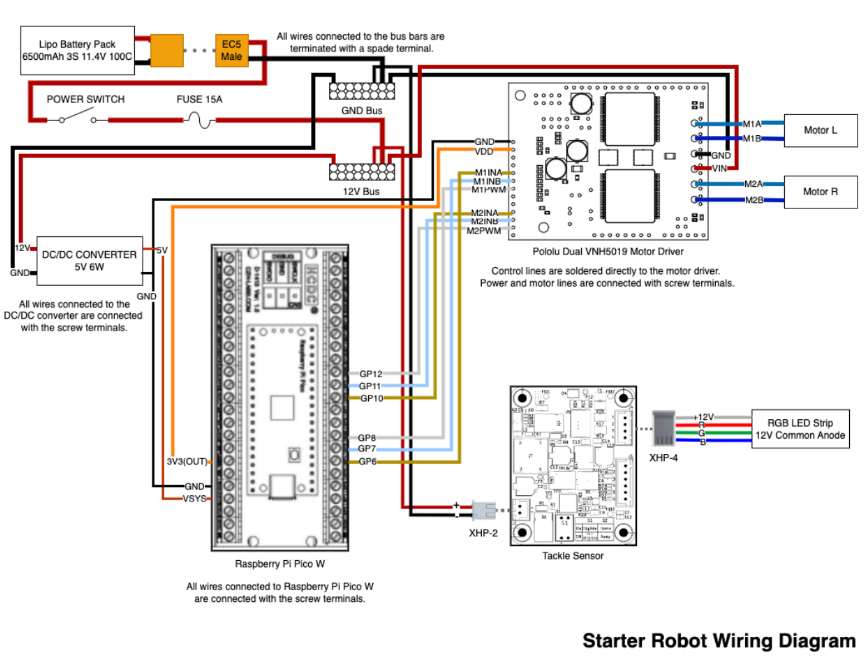
¶ Wiring Diagram
¶ Examples
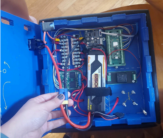
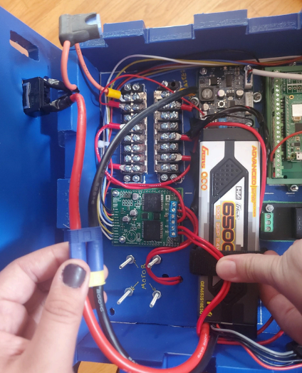
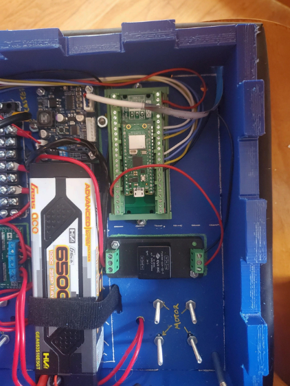
¶ Motor Driver Soldering
Parts Needed:
- Motor Driver
- Solder
- Smaller gauge wire
- Larger gauge wire
- Small gauge (big) spade terminals
Tools Needed:
- Soldering Iron
- Wire cutter/stripper
- Crimper
-
Turn on the soldering iron. (Rule one of soldering: Don’t touch the hot part. Rule two of soldering: If you drop it, don’t catch it. - Cara’s words of wisdom)
-
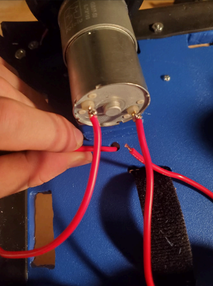
Cut four pieces (8-12 in) of your smaller gauge (i.e. thicker) wire, strip the ends, loop one wire through each of the motor connection holes. Twist the wires so that they are securely attached to the motor. Solder the wires to the motor (Note: it will take a lot of solder). Leave the other ends of the wires free for now. These wires will deliver the power and signal from the motor driver to the motors.
-
Cut eight total pieces (~6-8 in) of your larger gauge (i.e. thinner) wire (1 black, 1 red, 2 white, 2 yellow, 2 blue) and strip the ends. Make sure to use three different color wires to help keep track of signal wire connections.
- Black = GND
Red = Vdd (3.3 V for digital logic)
Yellow_1 = M1INA
Blue_1 = M1INB
White_1 = M1PWM
Yellow_2 = M2INA
Blue_2 = M2INB
White_2 = M2PWM
- Black = GND
-
Place each wire through the appropriate hole on the motor driver board. Solder each wire to its metal pad (Note: this will not need as much solder. After soldering, cut excess wire hanging past the soldered connection). These wires will deliver the controlling signals from the Remote Control/RaspberryPi to be interpreted by the motor driver before being sent to the motors.
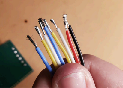
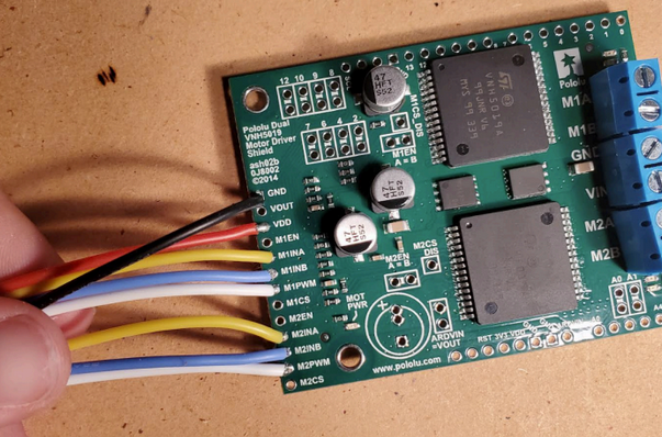
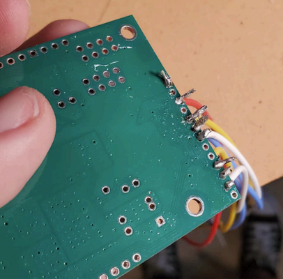
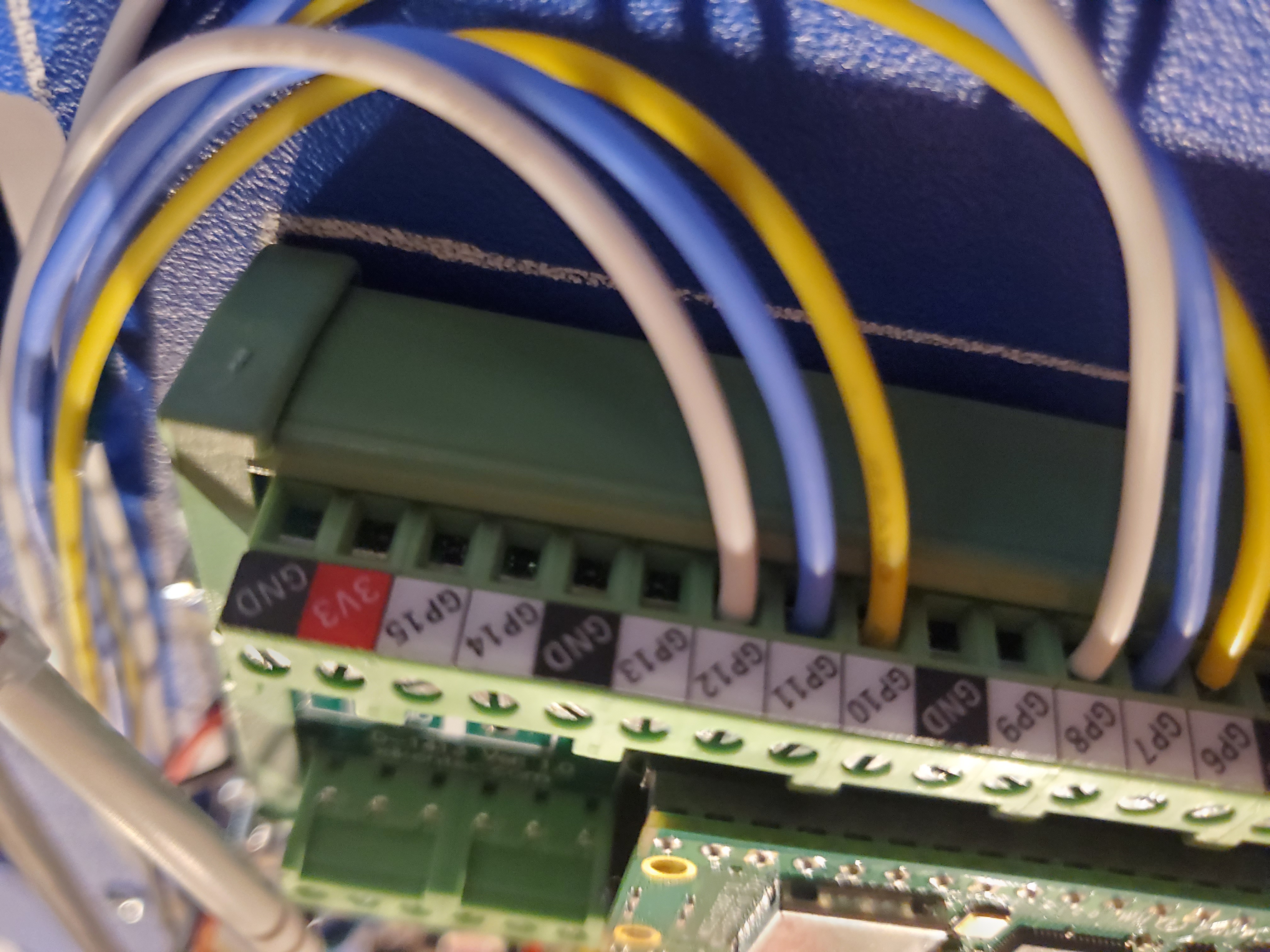
- Hook up your thinner wires to the RaspberryPi using the Pi’s breakout board screw terminals in the following order:
- Black -> GND (It doesn’t matter which GND pin you connect to)
Red -> 3V3 (it doesn't matter which 3v3 pin you connect to)
Yellow_1-> GP6
Blue_1 -> GP7
White_1 -> GP8
Yellow 2 -> GP10
Blue 2 -> GP11
White 2 -> GP12
- Black -> GND (It doesn’t matter which GND pin you connect to)
Note: It doesn't actually matter which GPIO pins you use, so long as you adjust the code and ensure that the white M1PWM and M2PWM wires are connected to PWM enabled pins from the Pi.
- Hook up the free ends of your motor wires to the motor driver screw terminals.
- Note 1: Each pair of motor wires goes into adjacent screw terminals.
- Note 2: Wiring the motors “backward” will not damage anything, but your wheels will not turn in the direction you intended. Solve this by simply swapping the wires.
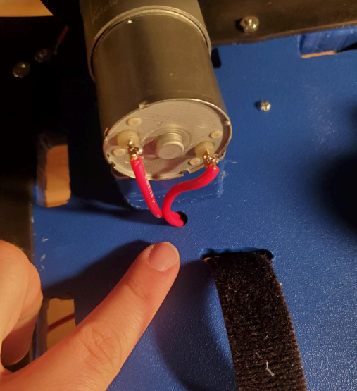
- Note 3: Make sure to thread wires through the bottom of the robot so the wires don’t get in the way of the lid.
- Cut two pieces (~4-6 in) of thicker wire (1 red, 1 black). Strip the wires. Crimp a spade terminal to one end of each wire. Attach the other bare ends of the wires to the motor driver using the screw terminals as follows:
- Red = VIN
Black = GND
Attach the spade terminal end of the red wire to the 12V bus bar and the black wire to the GND bus bar.
- Red = VIN
Note: You may have to cut one end of the spade terminal to get it to fit into the bus bar.
¶ Base / Bumper Assembly
Parts Needed:
- HDPE Base Plate (x1)
- HDPE Side Walls (x4)
- HDPE Top Plate (x1)
- Bumper Material
- Bolts for Bumper Mounting (x12)
- Nuts for Bumper Mounting (x12)
TOOLS NEEDED:
- Scissors
- Exacto knife
- Phillips head screwdriver
- Pliers or Adjustable Wrench
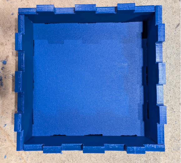
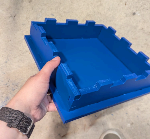
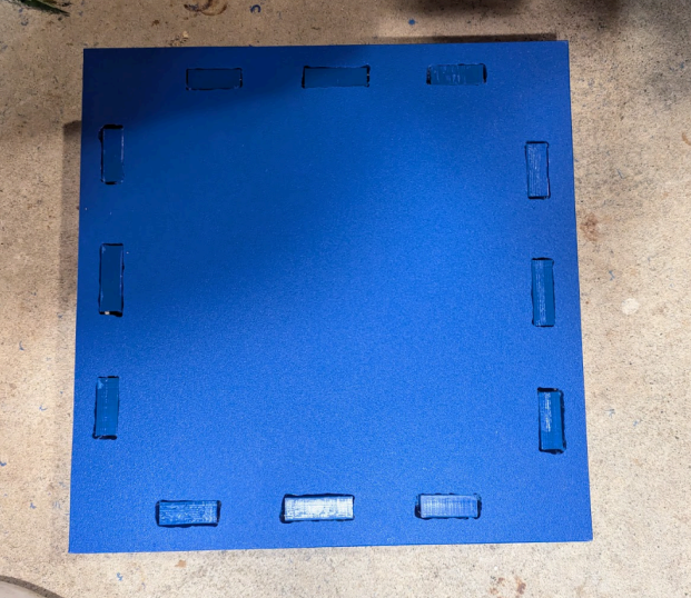
- Test fit HDPE Side Walls with HDPE Base Plate and HDPE Top Plate. If they don’t fit together nicely, file away material as needed for a snug but natural fit. See reference photos below.
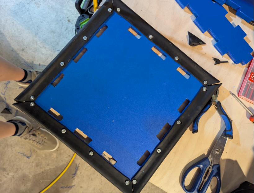
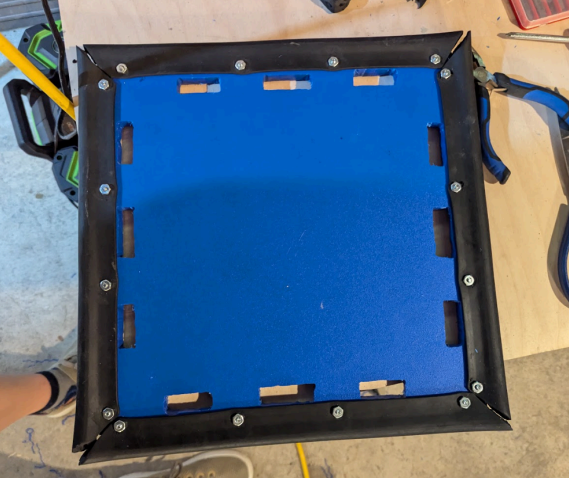
- Use Scissors to cut (x4) Bumper pieces to size using Bumper material. For context, the end result should look something like this once all bumpers are installed (which you will do in the coming steps):
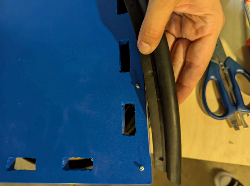
- Line up the cut Bumper pieces with HDPE Base Plate, and use Bolts for Bumper Mounting (or Exacto Knife) to mark the Bumper pieces where thru holes should be added to Bumper pieces (to match up with the holes in the HDPE Base Plate). Then, use Exacto Knife to cut out larger holes in those locations on the Bumper pieces. The holes must be big enough for the ¼” bolts to fit through them.
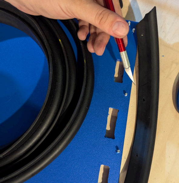
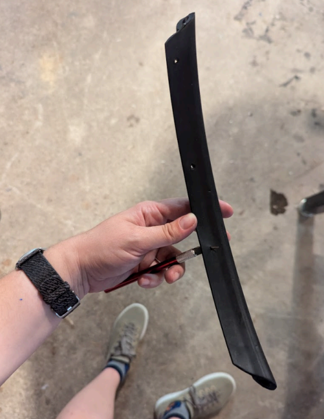
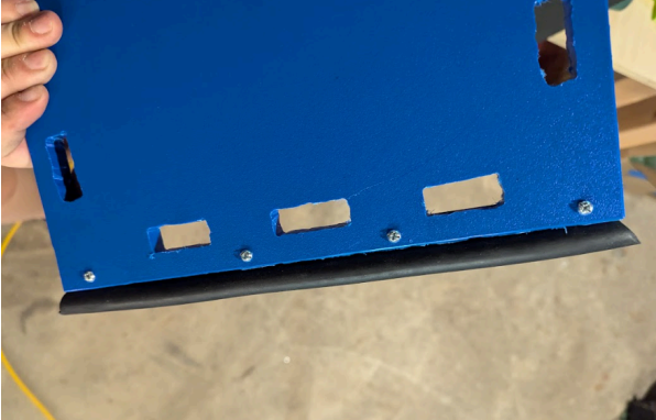
- Install Bumpers onto HDPE Base Plate using Bolts for Bumper Mounting and Nuts for Bumper Mounting. Tighten down using Phillips head screwdriver and Pliers (or Adjustable Wrench). See photos below.
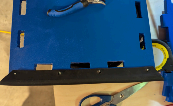
- Once the Bumpers are installed on the HDPE Base Plate, install the HDPE Side Walls on top of the HDPE Base Plate.
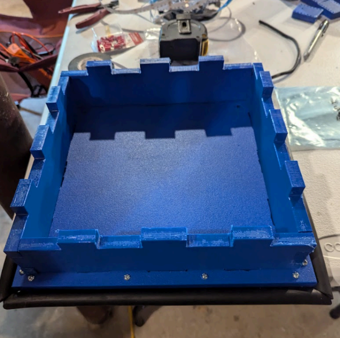
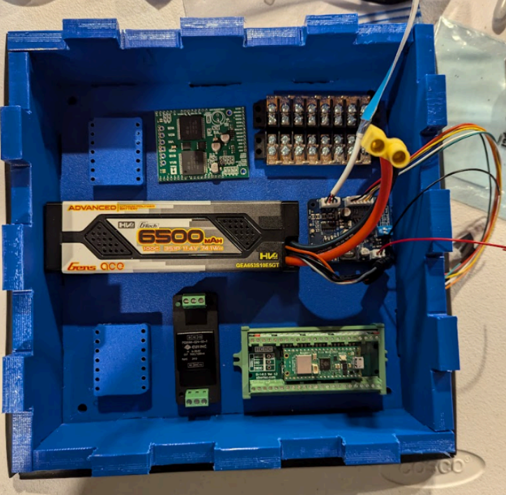
- (Optional but highly recommended): Test fit electrical components inside Base to ensure everything fits as expected. See example layout below.
¶ Motor / Wheel Assembly
Parts Needed:
- Motor (x2)
- Motor Mounting Bracket (and included hardware) (x2)
- Wheel Adapter (and included hardware) (x2)
- Wheel (x2)
Tools Needed:
- Phillips head screwdriver
- Allen key (2mm)
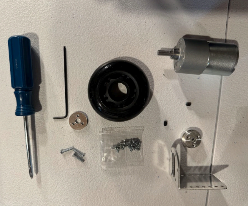
- Use phillips head screwdriver to install Motor Mounting Bracket onto Motor with bolts that came with Motor Mounting Bracket (see reference photo below)

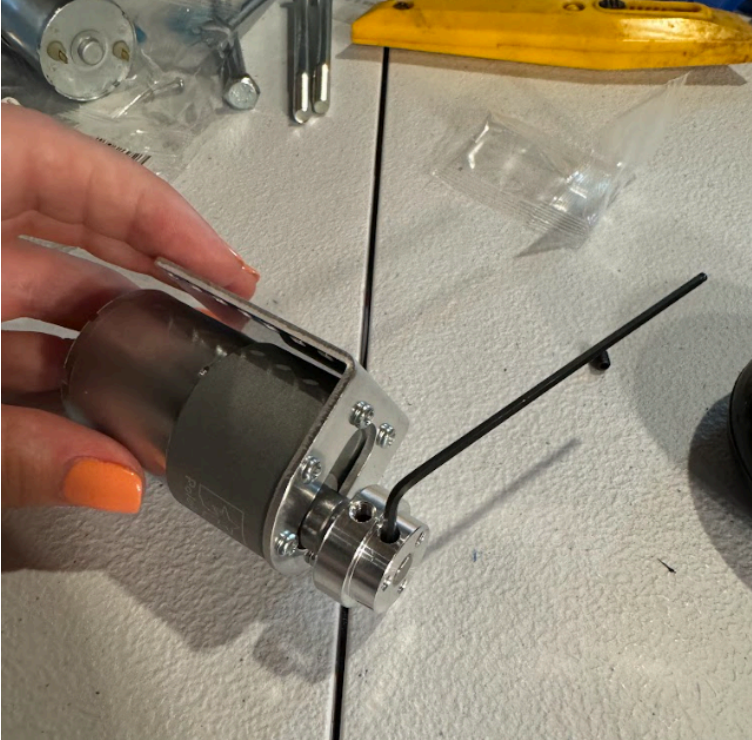
- Install Wheel Adapter onto Motor shaft. Ensure smaller diameter end of Adapter is oriented on the “outside” end of the motor shaft, as shown.
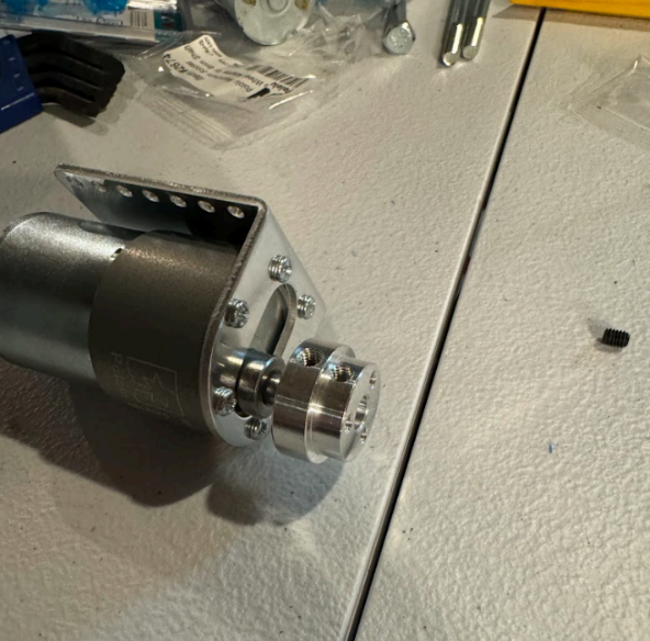
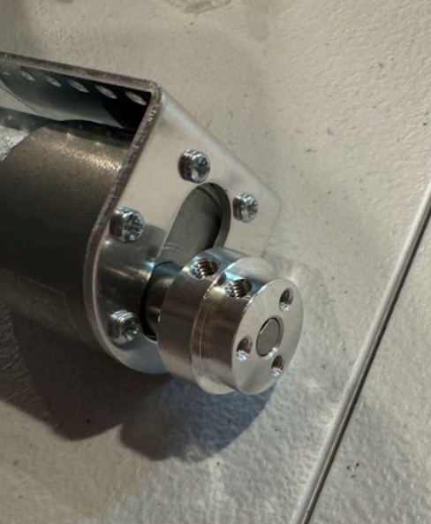
- Once the “outside” edge of Wheel Adapter is flush with the “outside” edge of the Motor shaft, tighten it in place using the set screws that came in the Wheel Adapter kit, using the Allen key (see photo below).
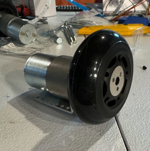
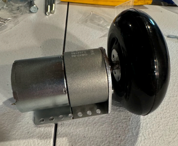
- Slide Wheel onto Wheel Adapter. Then slide on the Wheel Adapter Plate (from Wheel Adapter kit), fitting it into the pocket in the wheel. Use Phillips head screwdriver to install (x3) bolts that came in Wheel Adapter kit through the plate, into the Wheel Adapter, locking the Wheel in place.
¶ Mounting Electrical Components in Base
Parts Needed:
- Base/Bumper Assembly (x1)
- Motor/Wheel Assembly (x2)
- Motor Controller (x1)
- Busbars (x2)
- Battery (x1)
- Ball Caster (x1)
- Microcontroller (x1)
- Voltage Regulator (x1)
- Velcro
- Various hardware (reference table below)
- Motor Mounting Spacer (x4)
- Caster Mounting Spacer (x4)
Tools Needed:
- Phillips head screwdriver
- Pliers or Adjustable Wrench
Please reference the following two photos. The first photo shows where we outlined the locations of each component in the Base. You do not need to draw this in your robot. This is just meant to be a reference as you discern which holes are for what. The second photo is the end product, with each component mounted in the Base.
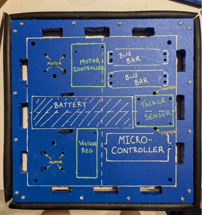
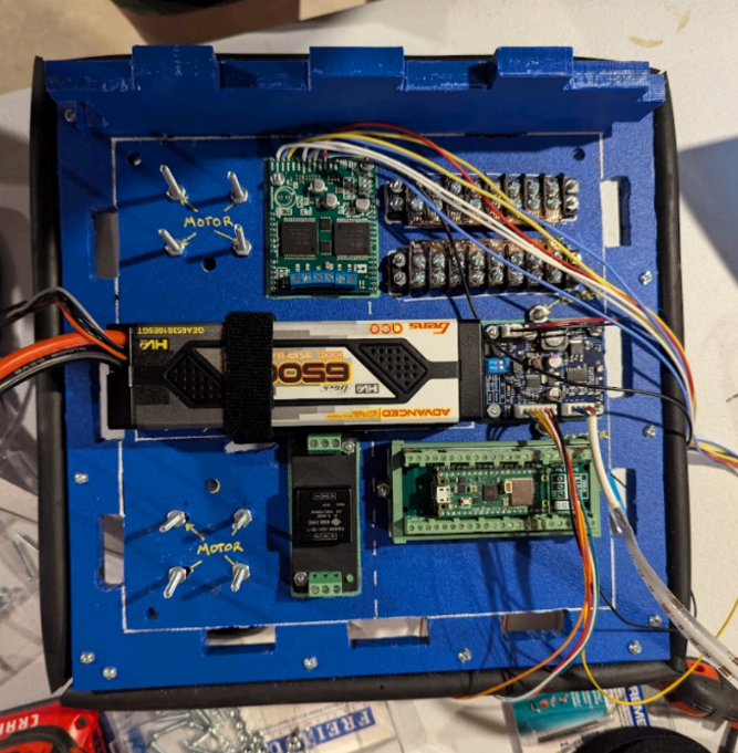
Use the following table to reference which hardware is needed to mount which electrical component. Install each component with the required hardware, using a Phillips head screwdriver and Pliers or an Adjustable Wrench to tighten the bolts snugly.
| Component Being Mounted | Quantity | HW Description | HW Specs | HW Qty to Mount One Component | Total HW Qty |
|---|---|---|---|---|---|
| Motor/Wheel Assembly | 2 | Bolt | #4-40 x 2.5" | 4 | 8 |
| Motor/Wheel Assembly | 2 | Nut | #4-40 | 4 | 8 |
| Motor Controller | 1 | Bolt | #4-40 x 1" | 2 | 2 |
| Motor Controller | 1 | Nut | #4-40 | 4 | 4 |
| Busbars | 2 | Bolt | #4-40 x 1" | 2 | 4 |
| Busbars | 2 | Nut | #4-40 | 2 | 4 |
| Battery | 1 | velcro | 3/4" velcro wrap (need 10") | 1 | 1 |
| Ball Caster | 1 | Bolt | #10-32x3" | 2 | 2 |
| Ball Caster | 1 | Nut | #10-32 | 2 | 2 |
| Microcontroller | 1 | Bolt | #4-40 x 1" | 2 | 2 |
| Microcontroller | 1 | Nut | #4-40 | 2 | 2 |
| Tackle Sensor | 1 | Bolt | #4-40 x 1.5" | 4 | 4 |
| Tackle Sensor | 1 | Nut | #4-40 | 12 | 12 |
| Voltage regulator | 1 | Bolt | #4-40 x 1" | 2 | 2 |
| Voltage regulator | 1 | Nut | #4-40 | 2 | 2 |
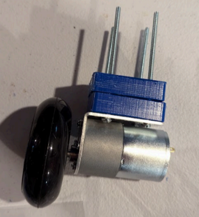
- Install Motor/Wheel Assemblies (x2) under Base, with (x2) Motor Mounting Spacers between the Motor Mounting Bracket and the bottom of the Base per motor, as shown below. Tighten snugly. (Note: the screws used in these photos are longer than the screws listed in the BOM. This was a change after our initial build)
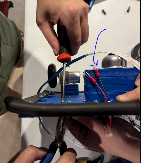
- Install Ball Caster under Base with (x4) Caster Mounting Spacers between the Ball Caster and the bottom of the Base, as shown below. Tighten snugly. When installed it should look like this:
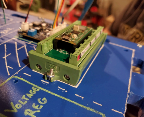
- Install the Microcontroller as shown
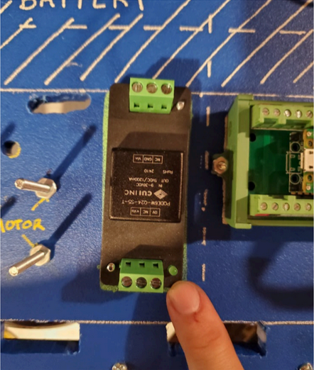
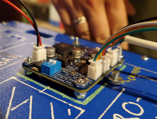
- Install the Voltage Regulator as shown.
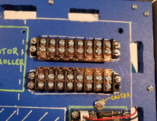
- Install the Busbars (x2) as shown.
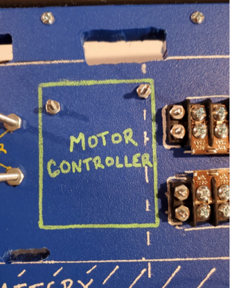
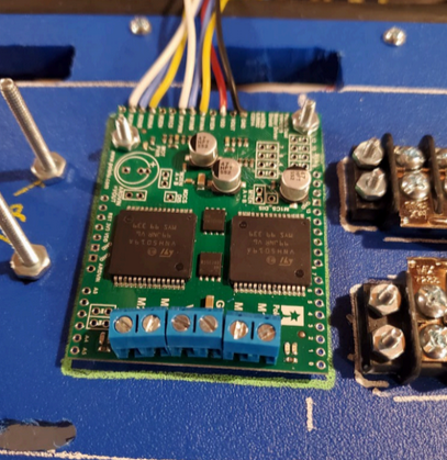
- Install the Motor Controller as shown. First, install the bolts with one set of nuts as shown below (which are functioning as spacers for the Motor Controller). Then install the Motor Controller on top of these nuts, with a second set of nuts (see second photo for reference). Tighten snugly.
- Install the Tackle Sensor as shown below – first installing two nuts per bolt (acting as spacers for the Tackle Sensor to clear the Ball Caster hardware), and then installing the Tackle Sensor on top, which another set of nuts to tighten it down.
- Install the Battery with the velcro, as shown.
¶ Helmet-up! (Final Assembly)
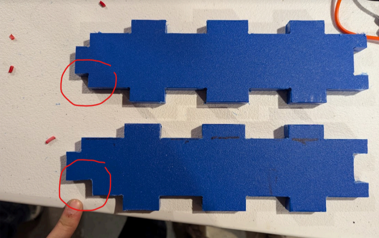
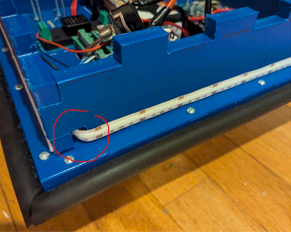
- In the robot CAD, all four walls are identical. To install the lighting, you will need to cut/drill a hole in one sidewall, and run the lights through to the outside.
-
Install the sidewalls. These puzzle-piece together to improve stability when your robot takes hits. If you connect all 4 together, you should be able to slide them down into the base as one. Note, if you have too tight tolerances on your CAD, you can always file down your pieces for an easier fit!
-
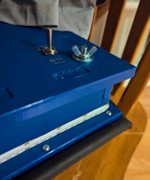
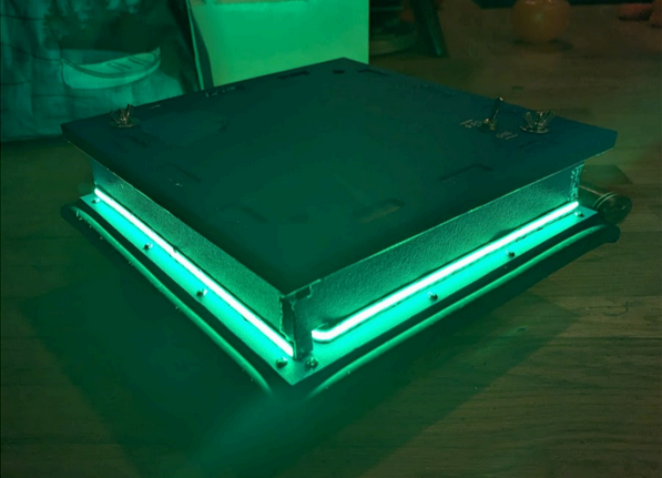
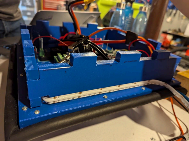
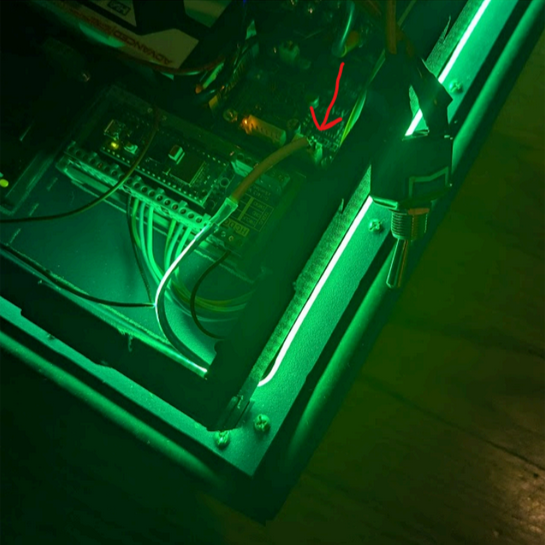
Plug the LEDs into the tackle sensor, run them through the wall opening you created, and stick them along the perimeter of the bot.
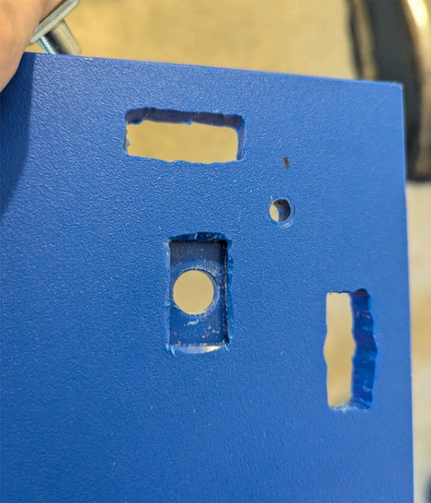
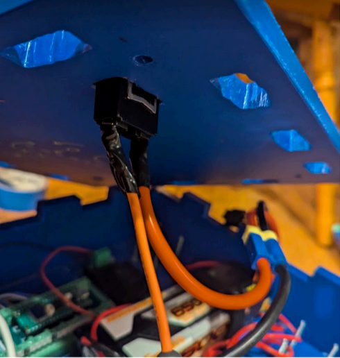
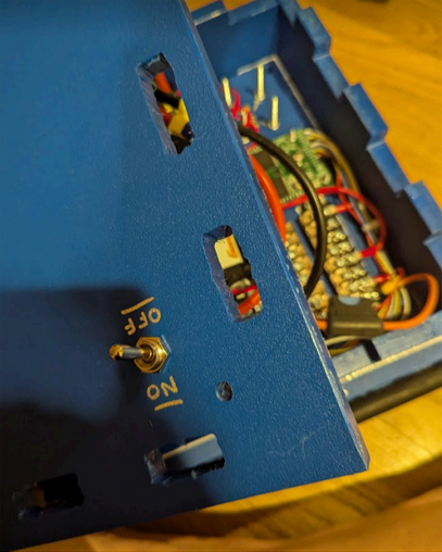
- Install the switch onto the lid. It should nest into the cutout on the lid to prevent turning, and the included nuts should be used to secure it from the top. Make sure it is oriented correctly to your “On” and “Off” labels!
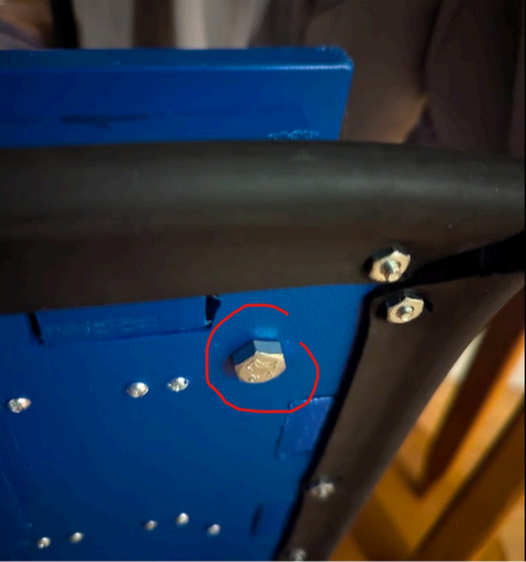
- Place the lid on the bot and secure the four corners with the 1/4" x 3-1/2" Hex Bolts and Wing Nuts.