¶ Starter Robot: Code Walkthrough & Programming
¶ Code Walkthrough
¶ Primary Control Loop
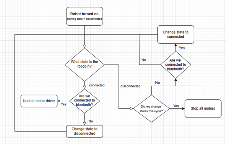
Below is a diagram representing the primary control loop of the robot’s code. The robot has two possible states, connected or disconnected. While connected, the robot reads the controller input as events and updates the motor driver based on the translated meaning of the inputs. If the robot is disconnected, it stops the motors and waits until there is a connection to bluetooth again.
¶ Reading Controller Input
The GitHub repository utilizes the btstack bluetooth drivers written for the Raspberry Pi Pico. The current state of the controller is stored in a struct called controller_state. The logic that converts controller input into motor driver inputs then reads fields from that struct to get the current values for all of the inputs on the controller. Specifically, we care about the values ly and rx, which represent the y value for the left analog stick and the x value for the right analog stick.
The method bt_hid_get_latest uses a common C paradigm of passing in a variable via pointers to be filled instead of relying on a returned value. That method is what looks at the incoming bluetooth data and updates the state of the controller. The specifics of the bluetooth driver are not relevant for this project, in fact, we leverage one of the most powerful programming concepts, abstraction, to allow us to rely on the library to work as the documentation indicates, and not have to focus on what is going on under the hood unless absolutely necessary. If you are interested in diving into how it all works, feel free to read through documentation online or the source code specifically.
¶ Converting Controller Input to Motor Driver Settings
Within the main application control loop, the motor driver is updated based on the state of the left and right analog stick, using the method update_motor_driver_from_control_input
The important concepts to cover here are motor speeds for going straight, turning and turning in place, along with the concept of dead zones for controller input to allow for easier use.
- Going straight: Moving straight forward or backwards is straightforward (get it). All that needs to be done is to spin the left and right wheel at the same speed in the same direction.
- Turning: Unlike a car, which turns by rotating its wheels with an axle, our robot turns by changing the relative speed of the two motors. To turn right, the left wheel needs to be revolving more quickly than the right wheel. In order to accomplish this, we tell the motor driver to spin the motors at different speeds. The same thing applies for turning left. The exact relative speeds can be adjusted to the team’s preferences.
- Turning in place: This works differently, to turn in place, the wheel’s need to be spinning in opposite directions of each other. To keep the robot in the same spot, they should turn at the same rate.
- Dead zones: Due to how the PS4 Dualshock controllers are manufactured, the base setting for the analog stick can correspond to different values for each controller. For example, one controller might have 0as its default value, while another could have 1. To standardize controls across all controllers, it is a good idea to include a dead zone, which is a band around these base values, maybe negative twenty to twenty, that is all considered zero.
Once the proper function is determined based on the inputs of the analog sticks, the aforementioned method converts the analog inputs to speeds to set each motor.
¶ Controlling the Motor Driver
The GitHub repository has a file, motor_driver.c, that controls the entirety of the interface between the pins of the Raspberry Pi and the inputs of the motor driver. Outside of the initialization function, it has three methods. The first, motor_driver_stop, simply sets motor PWM pins to have an output of zero. The other two, motor_driver_set_left and motor_driver_set_right, take in value, look at the sign of the value to determine motor direction, set the pin which controls motor direction, and then modifies the PWM output to match whatever the absolute value of the inputted value is.
The motor_driver_setup method is responsible for enabling all of the pins that control the motor driver. It enables the directional control pins for each mother (INA and INB) as well as configures the PWM inputs for the motor drivers. See the documentation for the raspberry pi PWM and GPIO control here: Hardware APIs.
¶ Programming the Robot
The firmware for this robot was developed using the C programming language. This project is set up to use CMake for building. The source code is stored on Github and git is utilized to track changes made to the project. There are a few steps needed to setup the build environment on the developer’s laptop, to checkout the code, to build the project, and to flash the code onto the RP2040.
¶ Setup Development Environment
The first step is to install the build tools for checking out the code and for building the software. This will vary depending on the operating system that is installed on the developer’s laptop (Windows, Linux, or macOS). Once that is complete, you can continue with the build steps.
¶ Windows using WSL
You can install Windows subsystem for Linux (WSL) and use that to build this project. This lets you run Linux distributions on your Windows machine without a virtual machine or a dual boot. Follow the latest instructions for installing WSL found on Microsoft’s website. Once this is installed, launch WSL and follow the Linux instructions to complete the project setup. Please note that some versions of Windows do not support WSL.
Alternatively, a new method for building with Windows has just been released from the developers of Pi Pico. The project currently does not support this method, but it should be possible to upgrade the project to use this method.
¶ Linux
Launch a terminal and run the following command to install all of the prerequisites.
sudo apt install git cmake gcc-arm-none-eabi libnewlib-arm-none-eabi libstdc++-arm-none-eabi-newlib
¶ macOS
Install the homebrew package manager for macOS. Follow the instructions available on the website to install. Once installed, launch the terminal and run the following commands to install the build tools.
brew install zstd
brew install cmake
brew install --cask gcc-arm-embedded
¶ Checkout the Project
In the terminal, navigate to a directory to clone the project. The project can be found on Github.
Clone the repo by running one of the following commands. If you have set up the git account using HTTPS, run the following command.
git clone https://github.com/Collegiate-Robotic-Football-Conference/starter-robot-firmware.git
Once this is complete, enter the project directory.
cd starter-robot-firmware
Once successful, update all of the project submodules using the following command.
git submodule update --init --recursive
¶ Build the Project
Every time that the code is modified, the project will need to be rebuilt so that the binary is up-to-date with the latest version of the code.
Create a build directory and navigate into that directory.
mkdir build
cd build
Build the project.
cmake -DPICO_BOARD=pico_w -DPICO_SDK_PATH=../pico-sdk ../
cmake --build .
If the build is successful, the logs will indicate the success. There will be a binary output in the build directory (.bin). There will also be a version of the binary (.uf2) that can be loaded via USB with drag-and-drop programming.
¶ Flash the Firmware
Find the file main_app.uf2 in the build directory. To upload via USB, hold down the BOOTSEL button while plugging it into the PC. This will mount a drive called RPI-RP2 to the PC. To flash the firmware onto the RP2040, copy the UF2 file into the drive by dragging-and-dropping it onto the drive. When the transfer is complete, the RP2040 will reset and the drive will be removed from the PC. The latest code is now on the RP2040!
See here for more detailed instructions on managing the device.
After powering up the RP2040, the LED on the pico-w will be flashing. This indicates that the controller is not connected. Simultaneously press and hold the Playstation Center Button and the Share Button. The controller will go into the fast flashing mode. Once the pico-w finds the controller, its LED will go solid.
¶ Debugging
Debugging is not necessary, but can be used by following this guide. Please follow the steps provided in this document. Some modifications to the build setup will likely be necessary to get this to work with the example.