¶ Starter Bot: CAD & Manufacturing
¶ Robot CAD
Here is a link to the CAD model of the starter bot: Starter Bot CAD
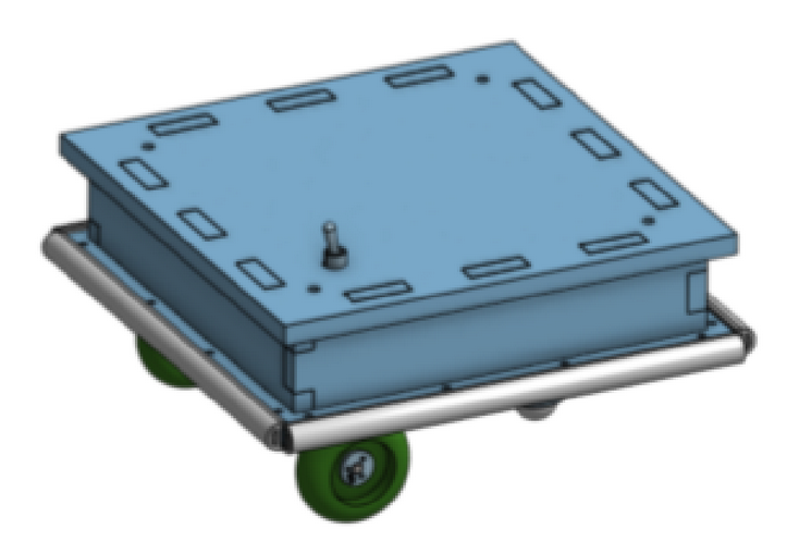 Isometric View of Full Bot Assembly Isometric View of Full Bot Assembly |
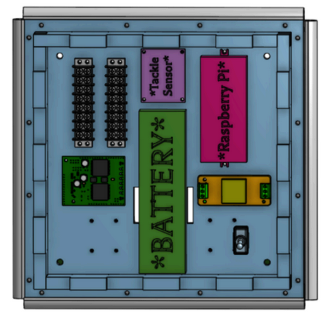 Top View of Bot Assembly (Top Plate Removed) Top View of Bot Assembly (Top Plate Removed) |
Onshape was used as the modeling software, as it is browser based, free to use, and has a collaborative mode where multiple people can be editing simultaneously. Many CAD softwares can be cost prohibitive, so Onshape is very accessible to everyone. Many universities have academic licenses available on university computers or student licenses available for download for a variety of different softwares (AutoCAD, SolidWorks, Creo, Fusion 360, etc.) Find out what software works best for your team and stick to one. Working in multiple softwares creates opportunities for lots of errors.
When creating a CAD model, you can put as much or as little time as you’d like into it. Generally speaking, the more time you spend in the CAD upfront, the less time you will have to spend during machining and assembly. It is much easier and less frustrating to fix errors and misplaced parts in a CAD model than it is to fix them in a partially assembled bot.
We created a different part file for each individual component that was used, assembly files for smaller sub assemblies (motor assembly, caster assembly, etc.), and finally one large assembly file that is a model of the entire bot. The large assembly file contains every machined piece and purchased component that goes into the bot. It also has every single hole used for mounting electronics, walls, and bumpers. Small holes for mounting can be hand drilled into the baseplate later, but when your team gets to the point of building multiple bots, the more you can take away from manual tools and move to automated tools (CNC routers, mills, water jets, etc.), the faster assembly will go and the more consistent the bots will be. Team members who are doing the assembly will thank you.
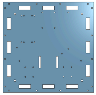 Part (Top Plate) Part (Top Plate) |
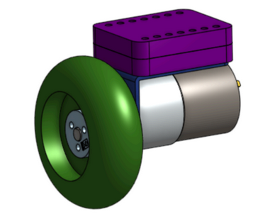 Sub Assembly (Wheel Mount) Sub Assembly (Wheel Mount) |
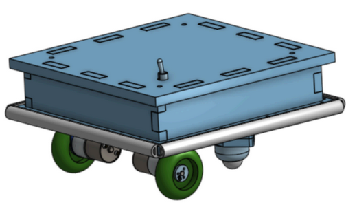 Final Assembly (Full Bot) Final Assembly (Full Bot) |
When making assembly files, you will constrain each of the components (part files) together. Constraints can be keeping one part a certain distance from the face of another part or making parts parallel to each other or the center of a bolt lined up with the center of a hole. There are many types of constraints. Use the type of constraint that makes the most sense for the component. Also make sure that you are constraining parts to something that makes sense. If you edit something, it can affect other things that are constrained to the part that you edited. For example, do not constrain your wheels to your battery. If you decide to move your battery, the wheel in the CAD model will follow, which may cause problems. Instead, constrain the wheel to the motor, since when the motor is moved, we want the wheel to move with the motor.
While in an assembly view, you can edit one part with respect to other parts (called In Context in Onshape). For example, in the assembly of the whole bot, you can create holes in the baseplate that are constrained to a component (bus bar for example). If done correctly, the holes are constrained to the bus bar, so if you decide to move the bus bar, the corresponding holes in the baseplate will follow. Taking the time to do this for all your mounting holes will make your CAD model dynamic and very robust. It allows components to be relocated in the model quickly without the need to constantly edit the location of holes
The best advice we can give you is to spend time upfront in the CAD model. Taking 20 minutes to fix something in the model now can prevent hours of improvisation later.
The final model of your bot should be extremely similar (ideally entirely identical) to your final assembled bot. If you made changes while assembling, make sure to return to update the CAD so the model reflects reality.
¶ Shell Manufacturing (CNC)
Now it is time to start bringing the CAD models to life.
All of the HDPE pieces must be cut out. The best way to do this is by using some form of CNC machining (router, waterjet, etc.) Find out what resources are available to your club. There may be university resources you can use, or you may have to outsource these parts. If you have access to using CNC machines, we recommend this route, as it is cheaper than outsourcing, and you will learn so much more.
The starter bot was machined using a CNC router, so these instructions will follow the programming of a router. If a different type of CNC is all that you have (waterjet for example), the programming will follow the same general concept, but will have changes that vary from machine to machine.
Some CAD softwares have the ability to generate CNC code and some do not. Use whatever software is available and is compatible with your CNC machines. If using a separate software, each individual piece will need to be exported from your CAD software to whatever file type your machining software can read (.dxf, .step, .prt, .dwg, etc.) and then turned into a file type that the CNC can read (.gcode, .nc, .lst, etc.)
After bringing in your parts to your CNC machining software, you will need to program the path that the machine will follow to cut out the desired parts. When using a CNC router, there are 2 main path types that will be used:
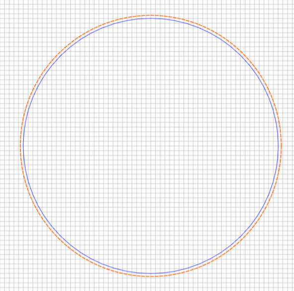
- Contour/Profile - this path will follow the very edge of a feature and will cut out whatever is inside of it without touching the material inside. It will separate the feature from the raw material. (think of cutting a shape out of paper) (blue is path of cutting bit)
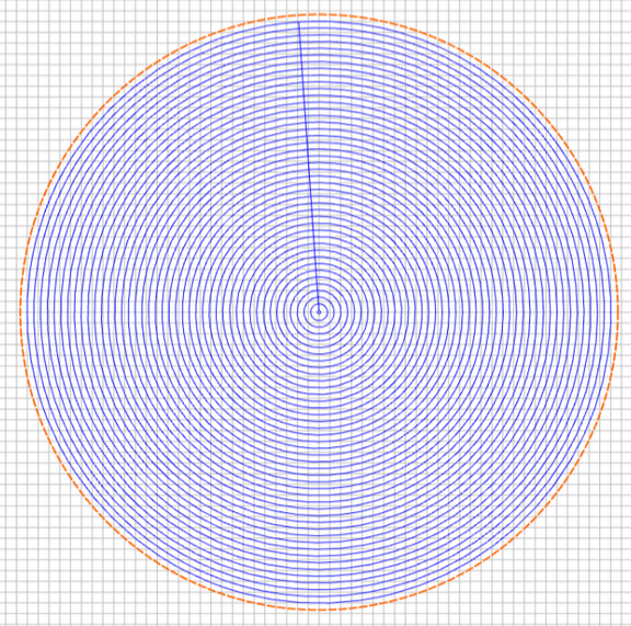
- Pocket/Roughing - this path will make multiple passes and remove all material inside of a feature, leaving nothing remaining. (think of mowing a lawn, nothing is left untouched) (blue is path of cutting bit)
With each path that you generate, you will need to select what size and shape bit to use. Most cuts will use end mills (cutters with a flat end). You will also need to set feeds and speeds that correspond to the size, shape, and number of flutes of your cutting bit. Calculations can be done to correctly select your feeds and speeds.
Here is a website that has recommended chip loads and feed rates (also called surface speed) for various materials including HDPE. Be sure to be very attentive the first time you try new feeds and speeds. Incorrect settings can cause errors in parts or broken bits.
- Chip Load: Amount of material removed per flute per rotation (measured in inches)
- Cutter: Also referred to as “bit” or “tool”. The changeable part at the end of the spindle that does the actual cutting. Often made from High Speed Steel and can have various coatings
- Feed Rate: Linear travel speed of the cutter in the horizontal (x and y) plane (inches per minute)
- Flutes: Number of cutting points on your cutter in one full revolution
- Plunge Rate: Linear travel speed of the cutter in the vertical direction (z)
- RPM: Spindle speed (rotations per minute)
- Stepover: During a pocket cut, the distance the bit moves over between each pass
You can run each part separately or you can nest everything into one giant file. This choice can be made based on size of machine, how much time is available to cut, or any other factors. This bot has been designed so that all pieces can be cut from a single 2 ft x 2 ft sheet of ½ in thick HDPE.
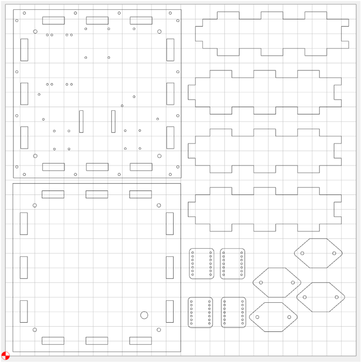
When setting up your workpiece in a CNC, it is important to square up the material to the machine. The machine has its own x,y,z coordinates, and it is important to line up the part to match. If this is not done properly, the parts may cut crooked or not fit on the sheet
Properly secure your workpiece to the CNC table. This may be done with screws, bolts, clamps, double sided tape, commercial adhesives, or many other methods. Whatever method is selected must hold down the piece very securely. If the piece is not secured properly, it is possible for the spindle and cutter to pick the piece up off the table. This is very dangerous and will often ruin your part. It is also important to secure the part that is to be removed from the raw material. Once the outside edge is cut, the part is not attached to the larger material, so it needs its own way of being held down.
Once your workpiece is secured, you will need to set your origin. When programming the CNC, you will have set an origin. You will need to tell the CNC where that origin is so it can cut everything where it is intended. Good practice is to use the same origin on each piece (I always use bottom left corner). If everyone on your team follows the same origin placing methodology, it reduces the chances for errors if one person runs someone else’s programs.
A limitation of CNC routers is their ability to cut internal corners. As CNC routers use round bits, they cannot cut sharp internal corners. It will leave a radius. This may be fine from an aesthetics view, but some interfaces will not mate properly. An example is the side walls mating to the baseplate. If these internal corners all have radii, there will be interference and there will be gaps between the connections. To avoid this, you can add manufacturing holes to internal corners. This is adding a small circle (just larger than the diameter of the cutter you will be using) to each internal corner. This allows the CNC to cut just slightly deeper into each corner and remove the material that will cause interference. Without manufacturing holes, you will be spending a lot of time sanding, filing, and grinding out corners.

CNCs are very powerful and very dangerous tools, and they must be treated with respect. They should only be operated by someone who is competent and trained at running them. Work with an expert while you are learning. If you are unsure about something, ask for help. Do not take shortcuts. Stay away from a spindle in motion. Take your time and do not rush.
No manufactured part is ever worth losing a finger.
¶ Tips
- BE SAFE and follow lab/shop protocols
- Secure your workpiece well
- Cut the interior holes of parts before cutting the outline. This ensures the part is still attached to the raw material and will not shift
- Always be within reach of an Emergency Stop
- Be extremely careful when handling cutters. They are sharpened on both sides, so they can very easily cut you
- Program in manufacturing holes to make assembly easier
- If you zero your z axis an inch or so above your part and do a dry run, you can make sure things look correct before actually cutting your material
- Work with your assembly team to find out what machining changes can make assembly easier in future iterations